More to come, I have just been busy with life.
More to come, I have just been busy with life.
More to come, I have just been busy with life.
Life is a little too dynamic.
This blog is not going to be updated for a while. Other matters are just too dynamic to allow a focus right now,

Making Cordless Tool Batteries Last
I may have mentioned this previously as part of another post, and I know I have raised the issue in 2 of my other blogs, which have this same basic post in them, but I am going to cover just the rechargable batteries as used in cordless tools and some appliances in this post. I did post this to my other electronics blogs, but after some thought, I decided to add it here as well due to the focus of this blog. This post is namely how to make them last as long as they were designed for. Why is this important? When I handle items being recycled at an organized collection, there are often numerous battery powered devices that are not that old. Why? For many, it is because the batteries have cooked out. This is the result of leaving an item on the charger contiuously until needed. From cordless phones, cell phones, power tools, and others.
I will just mention that if you have a number of “primary cells”/ batteries, and they are not going to get used for long time- put them in your freezer inside of a sealed plastic bag to reduce the potential for them tor dry out- this will make them last a very long time until they are needed. When needed, just let them thaw out before putting them into service.
To make the batteries last their longest, charge them fully with their charger they came with before first use. If the item is not going to be used for a while, just pull the battery out once it is fully charged. The reason why to do this is memory circuits can draw a great deal of current such as the IRobot “Roomba”. It maps while it does it’s thing and that map is retained in memory. Unplugging the battery does clear the memory, the tradeoff is the battery will discharge significantly in just a few days if left plugged into the machine.
Cameras are another item. The “Everio” cameras will discharge the battery in a few weeks or less even though the memory is not needing to draw current from that main battery, it is just the parasitic load of the power standby circuit. Charging the battery and then removing it from the camera will make it last longer. The memory sticks you plug into the camera do not require power to maintain the images. This is true of many cameras.
Now there are different technologies employed in these types of batteries. Different materials and constructions: however they share the same component in their electrolyte- water. I have dismantled many battery packs and it is not uncommon to find NiCads and NiMh types to have been boiled out- indicated by the mineral salts left behind near the venting holes in the cell. Most have a design life measured in “charge cycles”- if you circumvent the original design by placing the item back on the charger immediately after use believing that the battery must be kept up like that you will be replacing battery packs quite often and needlessly. Cordless phones and cell phones are a perfect example. NiCads also exhibit a “memory” when this “short cycling” is done which reduces the amount of use you can get from it later. The memory can sometimes be undone by discharging fully and recharging fully to “recondition it a few times, but once a cell has lost a certain amount of water- it’s capacity is greatly reduced and cannot be recovered by “reconditioning” it.
The short answer to extending battery life is to charge it fully initially, then leaving the device off of the charger until the power indicator indicates a recharge is needed, or if the device shows a very degraded operation- such as a cordless drill that barely rotates. Just because a cordless drill slows slightly does not mean to throw it on a charger- use it until you need to actually rotate the screw with the screw gun itself and only then put it on charge. While it may not seem fully practical on a construction site, you need to find that balance point because I am using battery packs that are about 10 years old in some cases.
Emergency flourescent lighting systems produced by a number of companies put a continuous float charge on the Nicads used by most of them, which cooks out most of them after a year, and since most are not made in a manner that lends itself to battery cell replacements, they are effectively “disposable”. I have salvaged a number of units and modified them for use elsewhere, but they are effectively similar in principle to the cold Cathode Flourescent lighting systems used in backlit LCD panels- be they laptop computers, monitors or TV sets.
Many public schools have tried to push kids into using tablet computers or laptops- these at best are going to be a yearly expense, and a needless one for numeorus reasons, but most school boards are not known to be intelligent nor able to make intelligent decisions, or the correct decisions. A black board or a white board do not need batteries to be used effectively. One has to question if the push to technology so early is due to a lack of teaching ability or a desire to keep kids quiet? Are they truly learning anything more than they would learn by way blackboards and whiteboards and an effective teacher? Based on what I see these days the answer is clearly “No”, just look at how many misspelled words there are in many newspapers these days, or sites with free ads. In My opinion, computers should not be introduced into classrooms until 7th grade at the earliest, and even then- only for students to learn some programing or code writing. Otherwise technology should not be a requirement until Freshman year of high school- even then limited in it’s use because the technology becomes a crutch.
But the problem with technology when it is in use is that of the batteries- most of the time people do not use their laptops or pad computers untethered from their charger. This means the batteries are getting constant current to refresh them but that is also forcing water vapor or Oxygen or Hydrogen even- out of the battery cells thus “cooking them” so they will never see the full life cycle capability of the battery.
Chargers have come a long way since the initial adoption of cordless drills in industry. But the chargers are not sophisticated enough to fully shut off when charging a partially charged battery, nor are they sophisticated enough to recognize a partially charged battery and either not charge or it will charge the battery as if it were fully depleted.
Now in home power systems, the batteries are mmot likely to be Lead Acid of some variant. The byproduct of charging any of them is hydrogen as a gas. The flooded wet cell types can be desulphated or “equalized” by an application of current at a potential above the “gassing point”. Usually above 16 volts for a 12 volt battery. Sometimes this requires pulsing initially to get the process started, but once begun, it can be very effective at salvaging some flooded cell types.
The lead acid variants should never be charged at an “Equalization” point as they are designed with a finite quantity of water assuming a finite charge cycle with specific charge potential requirements with essentially a finite life expectancy. Many back up power systems use AGM types of lead acid battery which are this sort of battery. Most of the time they are on a “float charge” when not in use- this gives them a very finite life span as it still reduces water in the electrolyte to hydrogen and Oxygen. These are NOT good sources for batteries for a home power system unless one is scrapping them in order to buy new batteries. Phone systems however change out their backup batteries (usually AGM’s) on an annual basis, and those usually have some potential for use in a home power system.
With Boeing using Lithium Ion batteries now in some of it’s new airliners, it is not long before we see some made for automotive or residential uses other than in the Hybrid vehicle’s battery systems, and many power tools due to their energy density.
Also, while these are quite common in power tools these days, they can overheat, as can Nicads or NiMH types. If they overheat, do not put them on a charger until they have cooled. Plus make sure you are using the correct charger for the Lithium batteries.
I will post more a little later about Nicad and NiMH battery cells and packs, there are a few tricks to save some of them and extend their life expectancy, but this post is long enogh as it is.
http://www.youtube.com/channel/UCdjcUtAAJ-CZVwaabB6SBpA
The associated blog for above youtube channel
http://altenciruits.wordpress.com/
The main blog.
the begining point place to start
http://altencircuits.wordpress.com/
The tangential blog.
http://passivesolarproject.wordpress.com/
The passive solar blog- outgrowth from some projects of mine.

Saving a Pad Sander
Most people have a pad sander or two laying about. When they work correctly, they are very useful, when they start acting up, they become a bit of a headache. Most are not made all that well, which is too bad. However some things can be done to fix them up to work as good as they ever could- namely the pad.
Normally, the pad holds the paper stationary to the orbitting pad, but the sanders usually have a sponge rubber pad that does not hold very well as it is too soft, or has had the corners and edges crumble, and the paper tends to tear, especially when the sander “grabs” the piece being sanded, especially when you get to an edge. Or if the corners and edges of the foam have eroded enough from use that they are no longer flat and make it a bit of a task to get the second edge of sandpaper under the clamp.
While some manufacturers do have re-padding kits available, it is just the same grade of material as what you are wanting to replace. In some instances that is okay if it is a better name brand of sander, but sometimes if you have some off- brand sander or you just do not want to put too much money into it; (which is not always a bad thing), this is a way to get it back in shape at minimal cost.
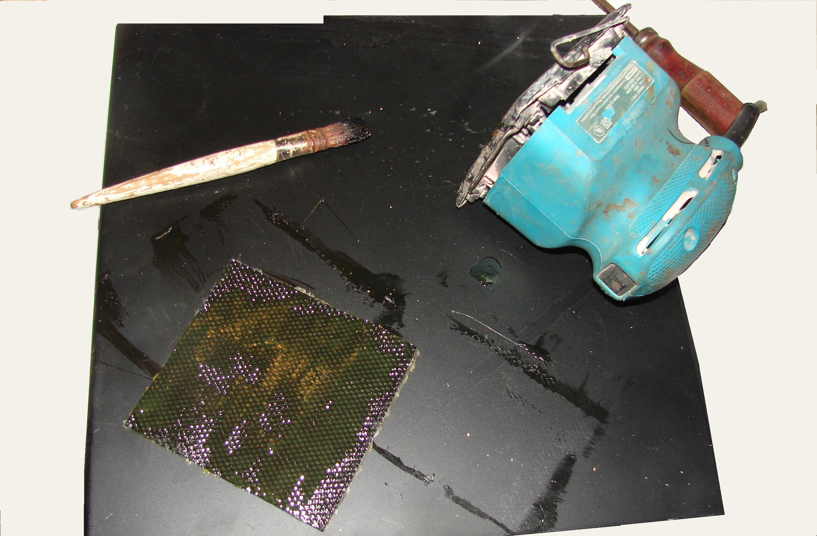
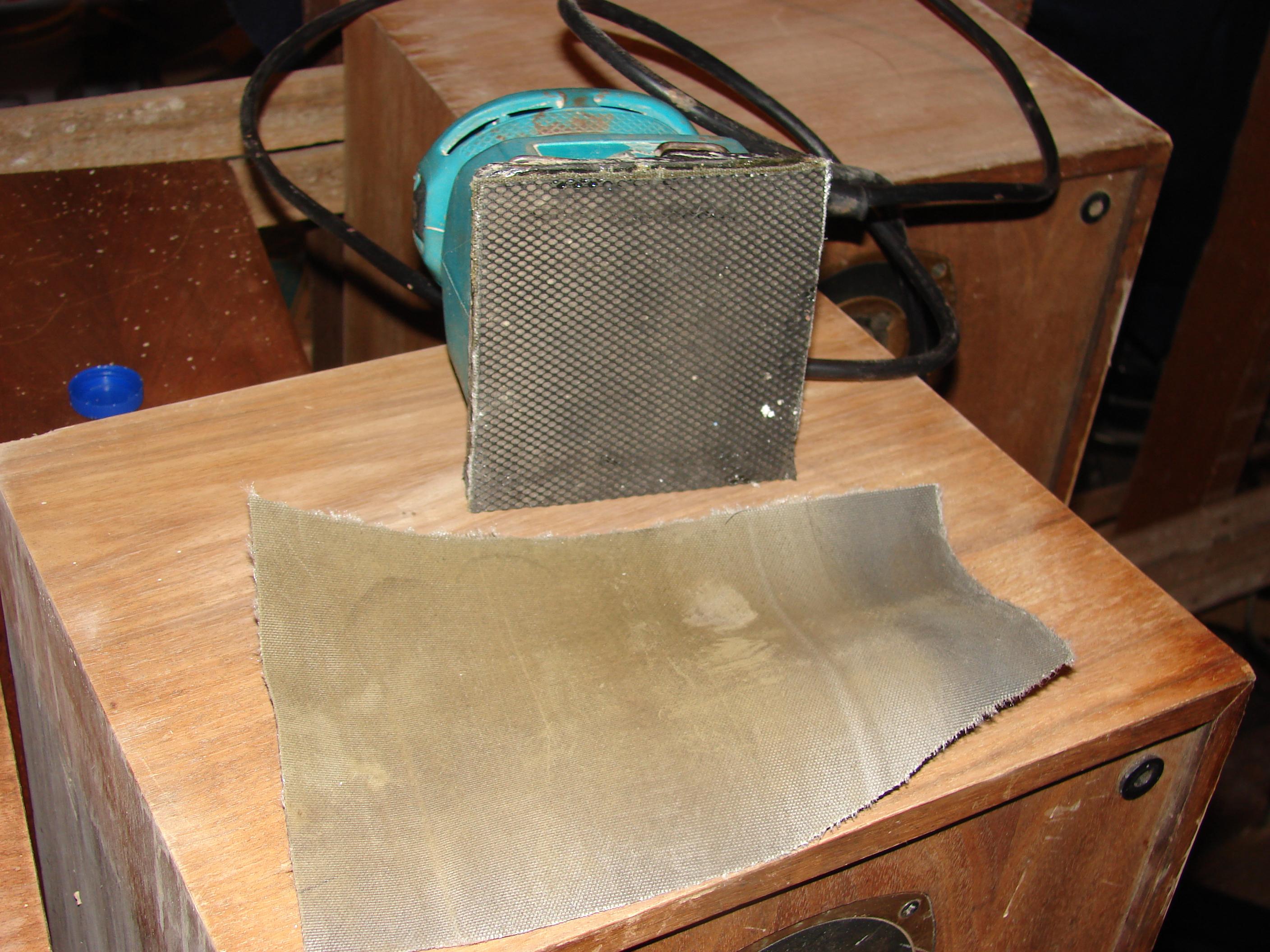
The simple solution in such a situation is to use an alternative material. These steps can also be done to make hand sanding blocks as well, which is definitely the sace if you are trying to sand a contoured piece of wood. What I used for the sander in this post was something that is not always available, but if you can find some it works very well. Treadmill tread. What is shown in the one image is after 2 pieces are glued together, and then the finished product with a chunk of treadmill scrap.
Other materials that can work:
Felt carpet square material if not thick- (1/8 inch to 3/16 inch). Regular felt is too soft and pliable.
Neoprene can work, but does not hold to adhesives very well in most cases.
Acoustic ribbed carpetting.
Cork can work for a hand sanding block, but wll not hold up well on a pad sander.
It may take some doing to scrape the old foam off, although the old one this sander had came off easily long ago.
The adhesive used in this case is just “Contact Cement”. VInyl and weather strip adhesive, “Duco Cement” or “Ambroid” will also make a permanent bond, but usually take a lot longer to cure and needs some clamping pressure while still “wet” or it will not bond flat. Do this outdoors or a well ventillated area as the odors from the contact cement or other adhesives can be overpowering. But once you have the pieces, the rest is just process. The back side of the tread as you can see is similar to canvas, this can actually be nylon weave or Aramid- better known as Kevlar. (You need a sharp scissor or knife edge to cut this well.) First just trace around the pad with a pencil or pen, and you will want 2 for this repair project. Coat the fabric side of the belt pieces with contact cement and let them dry to the touch. Once dry, you put the two fabric sides together and press them firmly, with them on the floor or a sturdy cabinet, push with the heel of your palm across the entire area, or step on them.
Then apply glue to one side of the glued tread and coat the bottom of the pad sander and allow those to dry. Once dry, carefully locate the sander over the replacement pad and once lined up- press them together. You really only get one shot at this, so be sure. You could use a corner of a box as a guide if you are not steady or don’t trust yourself to get them straight. If you cut the tread oversize slightly, then you can still trim to the hard pad of the sander later. Holding a box at an angle allows you to place your replacement pad in the bottom corner glue side up and then you use the two sides of the box as an alignment guide for the sander, pressing the sander onto the pad then once bonded lightly, just press the sander against a hard surface.
For hand sanding blocks, cut a block of wood to fit in your hand with comfort, then apply contact cement on one side, and to the treadmill tread fabric side (you only need one thickness for this), allow to dry, press together and trim off excess. Now you can wrap sandpaper over the edges for your fingers to grasp, the paper/hold the paper to the block, but the treadmill tread will hold the paper in place to the sanding block while sanding. If making a round sanding block for a curved contour, select something round that is slightly smaller diameter so the block with the pad applied matches the diameter of the profile. Smaller is okay too if just light sanding is all that is required.
When you apply the adhesive, you want it in as even a coat as possible without a great deal of thickness.
As for a performance evaluation on this “no-name” sander, it actually worked better than new. Your mileage will vary, but considering the area actually sanded without the paper loading up or tearing loose was in excess of 16 square feet and adequate to remove a thin layer of lacquer and still be ready for more- this exceeds the performance of many 1/4 and 1/3 sheet pad sanders when new (because thier pads are too soft). This was essentially 4 mid sized stereo speaker cabinets that I tested this on.
This repair will not work on those sanders that have perforations for dust removal unless you do not care about the dust removal aspect of that sander.
*If you need to trim the replacement pad, just use the hard plastic pad as the guide reference while carefully slicing with a sharp utility knife.
*Always cut away from you- never towards yourself. If others are around- make sure to cut away from them as well.
*Lastly as a general tip as this trick applies to many things that tend dry out in short order- Make sure the cover or cap is in on tight, then store the product upside down. The problem is light aromatics can escape through gaps that liquid cannot- but if that sealing edge has a “wet edge” (much like wines with a cork wine corks should be stored on their side to maintain a wet edge and keep the cork from drying out), those aromatics in many cements can no longer escape. Imagine using a can of PVC or ABS cement 2 years after you used it last- If you stored it brush side up: you know that will not work; but if you stored it upside down: That can is still liquid 2 years later (personal experience.). This works for contact cement, all lacquers, shellac, hobby enamels, and even can enamels.
And one of the common defects you will often you will find are dents in your veneers when working with plywoods or veneer laminated particle board, and sometimes in soild wood pieces. Sometimes the dent is actually a gouge, and the repair options are filler or veneer repair. I will cover veneer repairs later, but sometimes you want to raise the gouged material so you have something to work with or glue the repair to.
The solution for dents is a wet rag and a steam iron. This will lift most finishes and fillers and bond them to the rag, so best to use one that will not be reused for anything.


In the case with the gouge, that raised the substrate enough that I can glue a small repair patch of veneer into the spot. That repair is for later, so not covered here at present.
This will not raise all dents, but those that it can raise the steam will raise it. The most dramatic reuslts occur with solid wood and thick veneers. You can apply steam several times, but those areas where some of the veneer was actually scratched away, those will not recover much but you can sometimes see smaller dents than what you had. Sometimes the veneer is thick enough to allow you to sand out the remaining scratch, sometimes not, the steam will help. If you have legitimate plywood or solid wood core plywood, you can see on the exposed factory edge how much veneer you have to work with and decide whether to proceed or not. If you have particle board/wafer board- there is no guarantee that you can sand down to clear those scratches without burning through the veneer layer, or even sand to remove any finish as the old substrate may have deformed under that veneer leaving high and low spots (The Tannoy Speakers are that way).
The iron I used is a travel iron of 500 Watts set on “high”. Any iron will work, but best to use one that is NOT used for clothing. You do want to use care and not apply the iron to the wood directly as you can transfer material to the iron, or leave what was on the iron in the wood, or worse- scorch the wood.
http://www.youtube.com/channel/UCdjcUtAAJ-CZVwaabB6SBpA
The associated blog for above youtube channel
http://altenciruits.wordpress.com/
The main blog.
the begining point place to start
http://altencircuits.wordpress.com/
The tangential blog.
http://passivesolarproject.wordpress.com/
The passive solar blog- outgrowth from some projects of mine.

Off topic, but it lightens the mood a bit in a refreshing way…
While a bit off topic, it is one of those things that I figure is worth a mention here. If you do not like Ginger Ale or Ginger in general, you can skip this. I do have a post or two in the works, but these take time and I capitalized on the good weather outside as much as I could, which makes many of these posts delayed, so fear not.
A few years back a friend of mine gave me some “Ginger Drink” from Indonesia packed by “Intra”; because it was just too strong for her tastes or her husband’s tastes. I actually liked it mixed as per instructions. Plus the ingredient list was just 2 items- Ginger and Sugar Cane. Cannot beat that for simplicity, although I am sure if it were to be manufactured here in the US, the ingredient list would look like an organic chemistry exam, like too many foods look like these days anti caking agents, food coloring, artificial sweeteners, preservatives, etc. Funny thing about the additives- they really do not add anything to longevity and in many ways reduce the overall quality of the products they are in. Look at the ingredient list on a loaf of bread- something you can make out home with yeast, flour and water, maybe add some cinnimon, some butter and sugar for a swirl bread- which will last as long or longer than many of the breads with the long organic chemistry list once it is in your bread box. You do have to seriously question why some of the ingredients are even in there- such as “Sucralose” or some of the other offensive compounds.

Essentially I just washed about 2 pounds (it was actually just over a Kilogram) of Ginger root- about as fresh as one can find in out in the country; shredded it with a food processor, which made for two loads in the hopper. I litterally stuffed the shredded Ginger into an 8 quart pan, with 40 ounces of spring water (about 1.3 Liter). Brought it to a boil, let it boil on medium heat for 5 minutes and then simmered it covered for another 20 minutes on low heat.
When it was done simmering, I then scooped out the root and the inevitable liquid and strained that- pressing the mass gently in a strainer to squeeze out the liquid, I did sample the pulp just to see if there was much of the essentials left to maybe boil again- the simple answer is-no, don’t bother as there was not much left at all, so off to the compost it went. Unlike wine when you can make a “second run” with the mash, you cannot do that with boiled ginger root.
I had about a quart of liquid left, (maybe about 850ml),I let it cool first, but the next step was to try match the flavor profile of the Ginger Drink- which actually was not difficult. Using about 3 ounces of the juice, depending on your tastes, add anywhere from 3 to 6 ounces of water. or you can use seltzer water/tonic water for fizz. Then is the matter of sweetener. a 6 to 8 ounce cup will usually take 3 to 6 teaspoons of sugar to tame the taste down. If you use a low glycemic index sweetener like Stevia, Agave nectar , Honey or Maple syrup, the rough equivalence is in order. I would not insult the Ginger juice with an artificial sweetener ( one of the common artificial sweeteners metabolizes to embalming fluid and the other common one I have used as an effective insecticide- are you so sure you really want to use them at all? And I am not making this up, you can find plenty of references on the web which are legitimate and well documented.) Plus with the clean smell that is imparted to the kitchen as you boil this- are you sure want to add something artificial to muck it up?
You should be aware though- unless you are patient and try to filter the remaining suspended solids- the resulting unfiltered juice will look a bit muddy, which is only cosmetic. If you want to try strain it through coffee filters- you need to use very large filters or the paper clogs completely. Though wine finings can be used if you want to wait a week or two, but these solids are merely ginger root, so they are not going to alter flavor, or be a bother to you. A little lemon juice will help retard the oxidation as well, but I omitted it on the first run and it took about a week to drink the amount I made.
You can find other Ginger drink recipes on the web, few are as simple as this one based on a very simple and very good tasting drink mix- which also happens to be good for you. And if you know what I mean when I mention that “Ginger burn” from the better Ginger Ales- you get that with this as well.
This is just a simple recipe, it is not pretentious, it is not critical on amounts, so you can scale it as needed, though the fresher you can get the ginger the better the results. While it is as close as I can get to replicating the INTRA product, I know the consitency from cup to cup or glass to glass will not be as consistent as that of the commercial product, but it is close enough to be acceptable and refreshing, not to mention a bit more available.
The other thing about this simple recipe is you can make your own home made ginger ale from it, or whatever you please.
In a more conventional recipe format:
2 Pounds (1 Kilo give or take) Ginger Root
36 to 40 fluid ounces (About 1 L) water- essentially enough to just cover the ground ginger in the pot, so this part will vary.
Wash the Ginger and slice or shred with a food processor (you want a large surface area to the Ginger for maximum release of essential oils, protiens and starches that make up the Ginger Root).
In a larger sauce pan place the shredded, chopped or otherwise processed Ginger, and add enough water to cover the Ginger Root. Bring to a boil on Medium or Medium High heat, cover the pan and let boil 5 minutes on Medium heat then turn stove to low to simmer another 20 minutes. After that you can allow it to cool before you begin straining, or if you are careful, you can strain it while warm- this allows more of the Ginger essence to infuse into the water.
Pour or scoop the contents out and into the strainer with bowl beneath, either pour the liquid into a pitcher for later use, or for a starting point 4 ounces of juice mixed with 4 ounces of water with 4 teaspoons of Cane Sugar, and make adjustments from there to suit your own taste. I skip the Metric system for this part because you adjust things to your tastes. You can scale this smaller safely because the only significant rule of thumb is to slice the ginger and add only enough water to cover it in the pot.
http://www.youtube.com/channel/UCdjcUtAAJ-CZVwaabB6SBpA
The associated blog for above youtube channel
http://altenciruits.wordpress.com/
The main blog.
the begining point place to start
http://altencircuits.wordpress.com/
The tangential blog.
http://passivesolarproject.wordpress.com/
The passive solar blog- outgrowth from some projects of mine.

Space Heater Precautions.
I should have posted this sooner, and will repost this again early next winter with some revisions.
Some of the problems with older homes and some with newer homes is that of the wiring not being up to the energy demands of a space heater, or a space heater of excessive capacity being used on less than stellar wiring. This alone makes the idea of just using a larger breaker a really bad idea until you know for certain that the wire is an adequate gauge for the distance from the panel- most of the time it is not adequate to go larger.
One common issue, is the branch circuit supplying the upper floors of an older house is in their being wired in a “Daisy Chain” manner where only one power feed comes up, which is sized for a 15 amp total capacity for that floor. So that power comes up and may have an outlet on it before it proceeds over to an overhead fixture. From that fixture, a pair is dropped down for the switch- not a major issue, but then from that fixture is another pair of wires that go to a wall outlet, or other ceiling fixture in a closet for example. Then from there is goes to an outlet. From there it goes to another outlet, and maybe another, and then to the next room’s ceiling fixture, and then to another ceiling fixture in the closet, and then a wall outlet, and then to another wall outlet. And then from there, to another ceiling fixture, and another fixture in the closet, and then a wall outlet and then to another wall outlet, etc. If these are original, that installation was likely “grandfathered” in on any subsequent inspections. The wiring in those cases should be assumed to be inadequate for space heaters outright, so fo not put a space heater on that circuit anywhere. The simple reason is that the distance from the service panel can be very significant- in some cases such a run could be inexcess of 60 to 75 feet depending on the outlet. A 1500 Watt heater is going to draw 12.25 Amps, and 60 feet of wire is going to have significant voltage drop (resistance) and the toll of age on the wiring may also introduce resistance at connections at outlets and fixtures and heating at points where wire nuts, outlets and other fixtures along the run increase the chance for fire.

Now while this may be an economical use of wire, you can see how quickly the wire distance with associated voltage drop can become an issue. The issues as they relate to fire hazard do not develop instantly- they often occur over time- sometimes short, sometimes longer. Initially it may appear as an outlet or plug itself getting warm enough/hot enough to begin to soften and loose having lost structural integrity and just barely begins to melt and deform the plastic or insulation, and that can lead to a situation where arcing can begin to occur and that will sometimes lead to a fire, or the wire just gets hot enough to initiate ignition of flamable material in contact with it. Once an outlet shows an inability to hold a plug or show indications of being over heated visually by discoloring the plastic, (or has a melted plastic smell it should be replaced. But when that occurs, it should also be a warning that the wiring may not be adequate for the task.) The video I will associate with this post hopefully illustrates the issues that are not always easy to illustrate with words or simple artwork. Another potential risk is “Knob and Tube” wiring, which if the space where the wire is run has been insulated, it might catch fire from the heat of an overloaded wire, or the wood itself in some situations will be close enough to the hot wire to catch fire.
Another problem is sizing the heater. Many times the heaters are just too heavy of a load for wiring that might actually be safe enough with a smaller heater, even in a newly wired space or home. Eden Pure, and similar “Quartz heaters” are at least 1000 Watts. They often have a thermostat control, but not an actual heat control where you adjust the actual load. Some older style heaters have a switchable load, 300 and 750 Watts are common on some adjustable heat output units, and some newer quartz heaters do have the ability to switch between heat levels, but high is still usually 1000 Watts (8+ Amps) and often with a small insualted space, 300 Watts may be adequate heat, and as long as the outlet is wired with the conductor under the screw head, it should be “reasonably safe” that way if there is little other load on that branch circuit- no other heaters, no other high power lights or appliances, etc. The heaters themselves that are plugged in are never completely safe and people often forget that detail, and that is often the reason for so many labels on the units and the cords.
If there is an actual need for a temporary heat source in an upstairs space in an older home, the safer approach- though never completely safe, is to locate an outlet on a short run from the service panel with a larger circuit breaker and corresponding heavier wire: and plug in a heavy gauge extension cord (the outer jacket is marked as to the number of conductors and wire gauge) just long enough to reach the vicinity where the heater will be. 12 gauge or 10 guage wire in the extension cord will be able to handle a 1000 Watt heater with minimal issue if the run is limited to about 25 feet. Monitor the temperature of the outlet and the cords, the extension plug, the other end of the extension cord as well as the plug of the heater. If any of those items get warm, you need to monitor them for potential issues as they are already indicating heating from resistance in or load on the circuit. If much warmer than room temperature- unplug it and locate the problem. If they get hot enough to begin to show melting of the ends- unplug the cord, and the heater and inspect them for the cause, and replace any damaged components. If the heater is too large for the cord, go with a smaller heater after replacing any heat damaged end. The point where excessive resistance exists is where the wiring will fail and potentially cause a fire.
1000 Watts may seem well within the load rating of a 15 amp branch circuit, and technically it is, however, in some houses, be it the distance of the electric run from the service panel, or stab-ins in daisy chain- or both create a situtation where although it is “up to code”- it may not be safe enough for using that large of a heater. And some heaters are larger still.
To expand on why that 15 amp circuit may seem adequate, the issues arise from the accumulated distance(s) from the service panel introduce voltage drops that are additive, plus the fact that many outlets seemingly “wired to code” cannot handle a single significant load without the wiring or outlet heating excessively. This is because in many cases “Wiring Codes” allow for “Stab-ins”. While I mention this a number of times here, I have another post specific to outlets- which is intended as an instructional guide so you can understand how things work and how they should be approached. If you decide to do any work- you accept all respnsibility for that work. So if you do- make sure you do it carefully and competently.
“Stab-ins” just means wiring is stripped of a certain specified length of insulation and then stabbed into the back of the outlet or switch. The actual mechanical connection relies on friction between the spring piece and the incoming conductor to maintain the electrical connection. With light lighting loads, this is normally not a significant issue. However that connection- though “Code”, should not be considered adequate for a 1000 Watt or larger heater to be used on that circuit. Especially if you happen to be a renter- inspections are only looking at a minimum baseline, and are not looking for infallible/”bullet proof” installations. In my old house, I had issues with 2 outlets that actually fell apart and released one of the conductors from the outlet so all oulets were ultimately replaced and all of them I pulled out were “stabbed in” and ALL of them had indications of arcing with the wire when the outlet was dismantled. The new ones I installed I located the conductors to their correct location on the outlet under the screw heads, and the conductor being copper- required nothing special to achieve a superior result.
Now in some houses where the wiring is original and predates the “Stab in”, the wire conductor is placed under a retaining screw- when wrapped “clockwise” in the direction the screw tightens, as long as the screw retains tension and there is slight compression of the conductor- a good electrical connection is created, (and most stab ins still retain those screws- if you choose to upgrade that connection, that detail is covered in an upcoming post.). The issue in those homes may be accumulated wire distances, inadequate wiring gauge, or a sub-par repair between when the wiring was originally installed and today. Case in point- a freind’s home was wired by a not so knowledgable “do-it-yourselfer” (if you have the knowledge to size circuits safely and know what codes are, it is not difficult to do it correctly and safely.)
and they had a situation where the microwave (which should be on it’s own circuit breaker) happened to be wired with a string of multiple lights downstairs and upstairs. So what would happen is the breaker would trip when the microwave was used when lights were on in the basement and upstairs. A secondary problem was they used 100 Watt incandescents everywhere. Which raises another issue- light bulbs being too large for the circuit: Many modern plastic outlets specify 60 Watt light bulbs or less. When 75 and 100 Watt light bulbs get installed, the plastic and wire insulation begins to break down as well. While in the push to demonize the incandescant light bulb, all that did was close US industry- incandescent bulbs can still be sold legally and imported legally- even in the 60, 75, 100 Watt sizes. The law only banned manufacture of incandescant bulbs in those sizes within the US.
Any time I have repaired a “stab-in” be it a switch or outlet in my home, I always make it a point to place the conductor under the set screw of the new outlet and I make sure the connection is snug- torqued withing the range suggested by the manufacturer or code. On a few occaissions I have tried to re-use an old outlet out of economy- the few outlets I tried to reuse were usually a failure and fell apart before all the wires could be attached- so it is just easier to replace with new outlets, plus new outlets and switches are made to be used with a ground wire (even if only a 2 prong ungrounded outlet) so any exposed metal part of the switch including the cover plate screws that screw into it- are grounded. Just because a ground prong is in the outlet does not mean it is connected to anything- which is why a test light is useful. I will have images in the “Outlets” post to show the correct “clockwise” loop for placing under the screwhead.
Now some of the new types of safety outlet or panel breakers, such as “Arc Fault” or “Ground Fround Fault” Circuit interupters (these are two different types of devices, though somewhat similar.) exist, and some of these use an installation method similar to a “Stab-in”, but they are very different because the set screw actually is used and even though the wire gets stabbed into the device, the set screw applies tension in order to make a good electrical contact with the conductor and hold it in place. However some first generation devices are out there and quite old- they should be replaced. Especially if they are early first generation devices with “stabbed-in” wiring without a set screw as those items are now pushing 20 or 30 years old- they should be replaced for the sake of reliability and general safety.
I will caution you- if you are not familiar with electrical work, use care and always make sure the power is off to the circuit you are working on. To be safer- always use a test light or voltmeter to check to see if the outlet is still live with electricity. be sure to check both outlets of a twin or “Duplex” outlet because there are times when one outlet may be fed from 2 different circuit breakers. Or worse- someone wired 2 circuit breakers together at some point in their run from the service panel.
All in all, due to the potentially lethal nature of electricity- if you are not comfortable working with electricity, hire a pro- tell them exactly what you want to do. Codes do change, and some local code rules are a higher benchmark than the national codes. I myself have great respect for electricity, I know what it can do, so I have a built in sense of safety when working with it. Much of the safety in handling it and doing a repair are firmly rooted in common sense. Make absolutely sure the power is off before removing screws. There are some things I do for insurance that the citrcuit is dead that I will not get into here because I have seen some people do things in the wrong order and make mistakes in spite of when I have described to them how to be safe or how to do something. Electricity is one of those things where a single mistake can be your last. You do any such work at your own risk. I am just presenting this information to be informative and educational. So that if you do hire a pro- you know essentially what their process is ahead of time. And if you do decide to attempt it, you have some idea of what you are doing.
There will be another blog post soon about outlets in general, and I will discuss matters of wire color- which is very important, because the colors used mean something. Aluminum is also a factor and was used in some residential wiring outside of the manufactured housing industry and it had issues and has issues. But more in that post upcoming.
http://www.youtube.com/channel/UCdjcUtAAJ-CZVwaabB6SBpA
The associated blog for above youtube channel
http://altenciruits.wordpress.com/
The main blog.
the begining point place to start
http://altencircuits.wordpress.com/
The tangential blog.
http://passivesolarproject.wordpress.com/
The passive solar blog- outgrowth from some projects of mine.
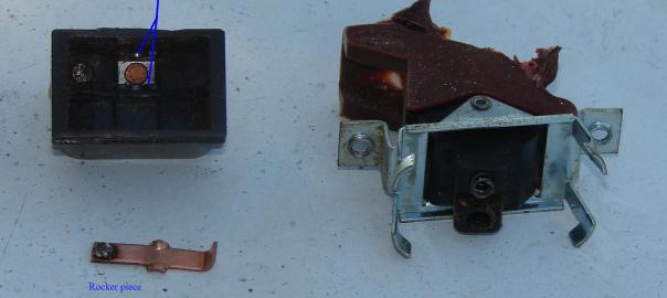
Table Saw Repair…
A While back, my old Sears 10 inch Table saw “gave up the ghost”, it simply stopped and flipping the switch back and forth a number of times did not get any noise from the motor. So I swapped a Delta “Super 10” Saw onto the base and ran that one for a while, until the motor capacitors failed. This being a tight budget situation required some thought on the matter as to which one to repair first. The Sears saw got the nod because I located a scrap Sears 10 inch saw that had a different top on it, but just happened to be the same motor and arbor mechanism. And having a decent table saw you can move around is almost an essential for a home renovation as well as for other projects.
The image shows the location of the 6 screws on the edges circled in red that retain the aluminum panel, there may be one or two others on that panel as the saws did have some variability. The two screws holding the protractor do not need removal as they only have a quick nut behind them and do not secure the panel in any way, so they can be left alone. The 2 screws circled in blue hold the switch.
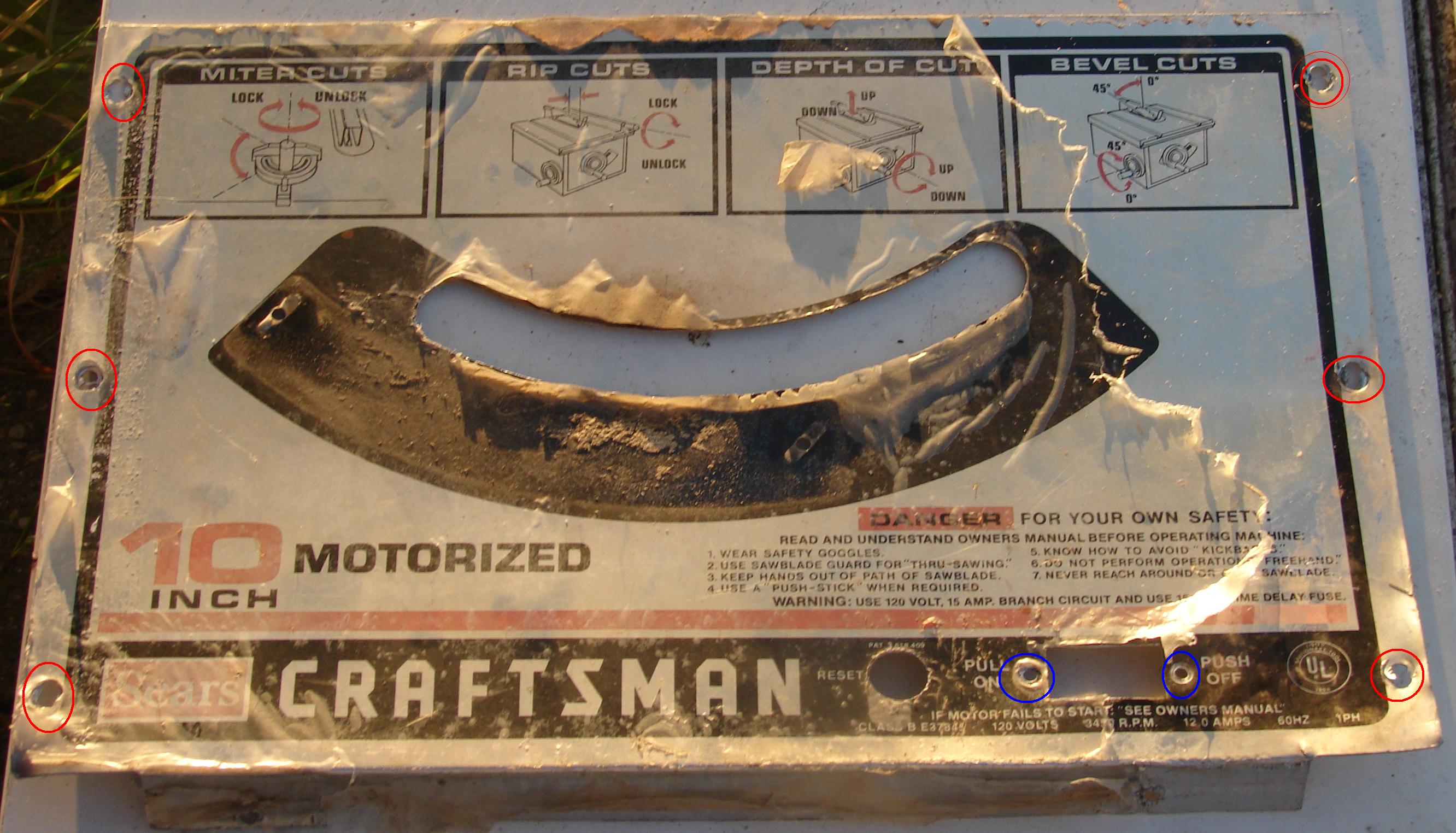
After some initial disassembly to get at the wiring for checks, which entailed removing 8 Phillips head screws that held the aluminum plate (as well as the sheet metal end of the saw to the rest of the base). The aluminum plat is what the switch itself attaches to with 2 philips screws of about a #6 size. The switch will not come out unless the yellow safety tab is removed. Slipping the two wires off of the switch freed the plate which was set aside for the moment as some cursory checks and a wiring diagram were written down. That aluminum plate itself- which once removed revealed decades of accumulated sawdust and essentially the compact assembly of the recess for the switch, the motor start capacitor, the thermal motor fuse/reset switch and the magnetic starter. The metal bracket under one of the thermal reset screws just retains the magnetic starter in place

Once the schematic was finished, it was simple matter of checking with an Ohmmeter the various potential culprits, which actually turned out to be the first item I checked- the switch. The parts saw was promptly pulled apart and that switch removed and once checked- it was revealed it too had issues, and was the most probable reason the donor saw was scrapped. This is a fairly general schematic as far as applications go. If you happen to have a newer power cord wired to an Asian or European wiring standard, double check the cord leads to be sure they correspond to the correct plug prongs, but most of those types will use the Brown wire for “hot” and the Blue wire for “Return” with the green wire with yellow stripe as the ground wire. In the US, the Black wire is the “Hot” lead and the return is the White wire.
However, this being a budget situation, I first tried some contact cleaner- I found later this was not even worth the effort, and hindered the efforts to clean out the sawdust. With the switch still showing no continuity when “on”, I decided first to take apart my old switch, which was melted from a fire (I actually bought the saw for the price I did because it had been too close to a fire, and it showed- which made people not take a second look at it in spite of the price at that garage sale. The fellow was pleased that the saw was going to good home- mine, and that I was not afraid of the melted nature of the cord or the switch and knew how to deal with them safely. I did get my money’s worth of work out of it initially before it started to act up. Once I had the original switch taken apart, it was actually very simple in design compared to some I have taken apart over the years and saw how easy it would be to effect repairs on the switch.

The one thing I would suggest if you decide to try this yourself, first put the switch in the refridgerator or freezer to chill it and thicken the grease that holds in the plastic pin which is missing in the photo. The image is missing the plastic button portion that rides against the moving contact. Chill the switch first and work quickly. you should not lose that button. Doing the repair outside is taking a risk and I admit I got lucky. The button must have shot out of the switch when it warmed inside of the solar gazebo where I parked the box of spares for the moment.
The problem is sawdust filters into the switch in spite of that foam seal. Both switches were fully packed with sawdust. Now getting the switch apart is easy, with a diagonal cutter or small screw driver, just bend the corner tabs that hold the rocker portion to the lower phenolic portion- bend them out enough for the tabs to be clear of the phenolic shoulder each anchors to. Gently peel the foam seal off the phenolic and tap out the saw dust. Compressed air might be a consideration if and only if you have the button and the copper piece that rocks to make the switch contact. It is that missing piece that rides on the back side of the rocker to make and break contact within the switch. As you can see, this one is quite pitted and therefore not used, since the original switch had better contacts, I took the best parts of both switches and combined them into one switch. If you are only dumping out sawdust, this whole process takes less than 5 minutes. Some degree of pitting is normal, but there is also a point where the pitting is just too extensive to even consider reuse. Dressing the contact with a “point file” might get some additional life out of the switch, but at some point an inevitable replacement will be needed. The switch is rated for 15 Amps, so you can replace it with a heavier switch to extend the life of the contacts of the new switch.
On reassembly, the rocker just sits on the pivots- make sure the botton contact is over the button contact on the switch body. Then reapply the foam seal and gently place the rocker assembly over the switch body- it is self aligning in most respects so all you need do once the top is in place on the body is push the tabs back over their resting places and the switch is ready to go back into service.
Since my original cord was melted, and I had a replacement cord, I simply undid the strain releifs and pull out the old cord. to undo those strain reliefs used, it is just a matter of squeezing the small tab that is visible towards the other portion of the strain relief that surrounds it with a plier or water pump plier just enough to allow for the relief to be rocked out of it’s hole. The replacement cord, which was salvaged from a plastic based Craftsman saw, just slipped into place. Both were 16 Gauge 3 conductor cords, so no issues there. If you replace with something that came from a different tool or source- make sure it is at least 16 gauge- 14 will work as will 12 gauge. If you are running the saw on an extension cord and simply want to incorporate that as the power cord- locate suitable strain reliefs- you will need 2, and enlarge existing cord routing holes and install cord. Then install the strain reliefs leaving a little slack between the 2 strain reliefs. If you are running a 25 to 50 foot cord- 12 or 10 gauge conductor will be a really good idea.
Reassembly is straight forward, the 2 slotted screw that hold the thermal reset fuse have a small brakcet that holds the mag starter in place. the screws only need to be snug- just enough to hold things in place while you are doing assembly. Now, neither saw had any issues with the mag starter or the start capacitor- if the start capacitor had vented at all, there would be the aroma of Hydrogen Sulphide (rotten eggs.). If a capacitor fails on startup, you will have large amounts of smoke billowing out of the saw cabinet in the vicinity of the switch. If there is a problem with the “Mag” starter, or if it gets wired incorrectly, the motor will run slow, noisy and hot. For this reason: only undo the wires that attached to the item needing immediate repair. The only other caveat just make sure your blade angle indicator is not stuck under the aluminum panel when reattaching the aluminum panel to the saw.
The industry part numbers for some of the parts are listed on the image, and these should be simply industry numbers in most cases- not Sears part numbers, so they can be located through motor repair shops, some online vendors, etc.
I did power the saw up after putting the saw back on it’s original base (4 bolts) and it started right up as if nothing had gone wrong with it. Considering the original handles for blade angle and blade height had melted off, I saw it as a good time to pull the handles off the donor saw and install them on the good saw. The correct handles made all the difference in ease of use, but if you are having some trouble with either adjsutment being stiff, just apply some motor oil to the threads of each adjuster and crank them to their extremes, and as always- store a table saw with the blade fully retracted below the table surface.
Since my saw dates from the 1970’s, I expect the saw should last at least another decade or two before needing work on the switch again. The capacitors usually have a date code inked on them somewhere, so if you really wanted to know the age of the saw, you can figure your saw was likely made about 6 months after the date code on the capacitor.
If the saw squeals on startup- the bearings are dry. The Sears 10 inch saws, the Rigid table saw of similar design and the Delta “Super 10” are direct drive motors- in other words the blade arbor is the motor shaft. (Some people do not like this approach, but it saves weight and costs and is reasonably durable. They may not be adequate for a large manufacturing plant, but houses have been built with less of a table saw or none at all.) The bearings are not within the scope of this post, but if you pull the end bells off the motor, you can see the bearings. If they just make noise, but are still smooth in rotation, you could try regrease the bearings (if ball bearings) by gently pulling the dust seals off one side of the bearing with a flat dental pick or small screw driver- use care not to damage the inner race sealing lip and then repacking them much as you would a wheel bearing- use a short fiber grease or one with Molybdenum Disulphide and pack it full -after applying some solvent to remove the old grease residue. Once repacked, then it is only a matter of straightening the old dust seal and slipping it back on the bearing once you are sure there is no damage to the inner seal lip that rides on the inner bearing race. Never apply compressed air to a “dry” bearing that both races are secured against rotation or damage that can affect the life of the bearing can occur.
Older saws sometimes use ball bearings to support the arbor, and these are usually marked on the outer race as to what their part number is if you choose to just replace them, and then it is only a matter of slipping them off the shaft or out of the arbor casting- which is aided by a wood mallet or plastic faced hammer. Older saws used sleeve bearings/bronze bushings, which if they run dry will make noise, and these are just a matter of a few well placed drops of oil to take care of them in most cases- unless there is too much radial play. In that case those need to be driven out and new sleeve bearings of the correct size gently driven in. There should be minimal axial play (side to side or end to end of the arbor shaft), but there should be about 0.010 inch clearance so the arbor can spin freely. This is adjusted by loosening the arbor pulley and moving it closer or away from the arbor casting.
Further adjustments and tweeks will likely come later as they take some time to perform them correctly, and my saw is still in adjustment, plus some of the adjustements that can be made on other saws cannot be made on this saw due to how it was manufactured.
http://www.youtube.com/channel/UCdjcUtAAJ-CZVwaabB6SBpA
The associated blog for above youtube channel
http://altenciruits.wordpress.com/
The main blog.
the begining point place to start
http://altencircuits.wordpress.com/
The tangential blog.
http://passivesolarproject.wordpress.com/
The passive solar blog- outgrowth from some projects of mine.

A surplus scrap from one project inspires another useful project.
This is just a short post, and it is the result of an application derived from “leftover’s” of another project in the works for the Passive Solar blog.

I have a number of pieces of “mechanical polarizer” left over from some lens assemblies I have acquired from various rear projection television sets. They are thin, faily lightweight, and for those areas that you want to reduce heat gain in summer, but allow heat gain in winter- these are perfect for that as they can be removed fairly easily if you use a light to medium tacking product like 3M’s ATG. While it is made for an applicator gun, you can apply it like you would 2 sided tape. You should be able to purchase some from your local picture framing shop, framing supplier- if you buy by the case- just check to make sure they have a “City Desk”(sometimes they may ask for a tax ID number). Be aware though that this product is not cheap.

The image is taken after the assembly, and your eyes will get “bendy” looking at it, but you can see the adhesive is reasonbly transparent.
This also gives you privacy. If used in a bath window or bedroom. or a door, the closer you approach them, the clearer you become from the outside; as an outline at first, but until you actually contact the sheet, details are not clear. Much like “Ribbed” glass. Now there are a couple of types of polarizers, some are just perforated plastic, which in a dark room are going to cast images of the outdoors on the darkened walls in much the same manner of a “Camera Obscura”. Others are variations on linear prismatics, much like the above image.
All of these will reduce the amount of transmissible light, usually comparable to less light than a “sheer” curtain, but a little more light than a simple paper accordian shade. Plus the advantage that some light gets reflected back outside and the polarizer will absorb much of the UV light as plastic is known for, and the amount of light entering the room is much less. I would estimate about 50% less.
And the real beauty of them is the fact you are taking an item that is often considered just scrap or garbage.
All you need to do is trim the piece to fit either the window sash (apply ATG to all 4 sides, and do this in winter when it is cold outside as well as dry inside.), which will give you an insulating “Dead air space”, which will automaticall put your sash into the same realm of performance as modern windows.
Or do as I did and trim it to the size of the glass that is visible within the sash, and adhere it to the glass- 2 strips of ATG, or 4 strips along the edges, (but your dead air space is now less when comapared to sizing to the sash, but still present when you use 4 strips of ATG A dry day in winter is best for the 4 strip approach- make sure in either approach with 4 strips of ATG; the adhesive must overlap at the corners so they create a seal.). I cut my polarizer sheet with a scissor (it is that soft), so it is easy to trim. I did it quick with a scissor for this post, but in the future with other windows I will use a straight edge and utility knife. However, even though the plastic is soft, the plastic is brittle and can break along the prismatic ribs, so scoring and bending is sometimes an option. But a sharp utility knife with a good straight edge can do the job very accurately and cleanly. If you are not careful- especially with the type that is perforated plastic, they will start to tear, split or rip, so you do need to keep work areas flat, and handle it carefully from the top edge.
In the image below, the window on the left has polarizers, and the window on the right has none. Both have air conditioners. The left window, the upper pane has an unsecured piece that is largely held in place by the sash lock at the bottom and bubble wrap scraps in the middle stuffed between panes as it is there only for the cooling season. The windows in general are in tough shape, but they will be addressed in the future, as they are going to be repaired when I move the remediation/renovation into that part of the interior space.

The other big plus is once the lenses are removed from the TV cabinet, and the mirror removed, that cabinet can be knocked apart to reduce consumed space which can be a cost saver when it comes to the recycling of the rest of the set. If however you are salvaging other parts of the set as well, you just have 3 projection CRT’s to send away. That cost of disposing of 3 CRT’s in a legal manner versus the cost of the whole set intact can justify the effort in itself.
The coolant used on the face of the projection tubes is a Silicone based oil, it does have a high vapor pressure for a liquid, so you can evaporate it to get rid of that. It could be used as a wood preservative, but I make no assertions as to how often you would need to reapply it. You could also use it as a low residue oil for fans, but again, in such duty I have no idea how long it will last or hold up as a lubricant. It could be burned as an oil fuel safely enough, but you may have some glassification of surfaces as a byproduct of combustion.
All in all, this is just one constructive use of a product that you may not encounter very often, but when you do encounter it- you will now have some ideas for putting to use. Not to mention that you may be able to find some sources for little or no cost among certain groups of experimenters.
As for what I did with the Fresnel lens from the set- check out the “Solar Furnace” in the “Passive Solar Blog”.
You are only as limited as your imagination is.
http://www.youtube.com/channel/UCdjcUtAAJ-CZVwaabB6SBpA
The associated blog for above youtube channel
http://altenciruits.wordpress.com/
The main blog.
the begining point place to start
http://altencircuits.wordpress.com/
The tangential blog.
http://passivesolarproject.wordpress.com/
The passive solar blog- outgrowth from some projects of mine.
Some Random Notes
While the voice is still a bit of an issue preventing video production to this point, I am clearing out some of the time diverting projects that have come up in the normal course of events that have kept me away from more posts than I have put up so far. I will figure something out to remedy the voice issue, the other matters I just have to grind through them.
Work progresses, some of the budgetary issues have been addressed, but not all of them. But this is just the reality for anyone trying to do a needed repair when on a shoestring budget.
However, in spite of all that, there are some posts in the works that are a little bit conceptual, but are very real considerations for anyone in an older home. One of the forthcoming posts is in regards to space heaters, but the concepts covered apply just as well to air conditioners.
Another post addresses just wall outlets. And while that may seem trivial, it really isn’t; especially in homes that were wired during the REA and RTA eras of post WWII in the US. Even newer homes wired to “code” may not be safe enough to handle the load of an AC unit or space heater. I have not decided on whether to add in some tidbits of radios and lighting intended for European markets that made their way here to the US or not, or if that will be a seperate post because there is some similarity.
There will also be a number of posts concerning wall treatments, and how to create them. This would also have a little bit of a discussion about color choices, and period correct finishing touches. Some things that are definitiely “Mid Century Modern”; as an example; are going to be out of place in older homes, but some “newer homes” might benefit from some of those “moderne” touches, or even older “Art Deco” touches. After all, some of the influences of the “Danish Modern” design concept are still around in modern home design and renovations, and some of the newer technologies just lend themself so well to “Art Deco”. But other things things like “Soffits” in a kitchen built prior to 1965 are really out of place in older homes, but are just fine in homes built after 1965. The years are not “hard and fast” as there have been some exceptions, but I am addressing more in a general sense of “when it was universally accepted” as a design feature. Soffits being wasted space? No argument there, but it did allow for easier installation of wiring and recessed lighting.
Plus, people sometimes forget that much of what is done today to restore a home to period correct appearance is usually undoing something that our parents, or their parents or their generations had done trying to “update” things like kitchens, windows, additions, etc. And to be blunt and honest- they really did not have any sense of history of the structure, (or of the period design prevalent when the structure was built) when many of the “renovations” took place.
Attitudes have changed, and merchants as well as manufacturers now cater to that restoration/preservation sensibility that more people have these days. And with an eye to history, many of those “renovations” were done to “forget” the past. After all, during WWII: 1942 to 1946 more accurately; there was rationing of just about everything, and some things just were not available and those generations of people wanted to forget those times. That is one reason so much woodwork was painted- real wood with varnish was “old fashioned” and the media after the war promoted “forward looking” and modernization, and as a result a great deal of paint was sold. And in the 1970’s, people were pushing for “efficiency” in lighting- hence the big ugly “floating” flourescent fixtures or kitchens with drop ceilings and office like trough lighting. And many of the houses and apartment complexes built during that time period are not entirely appealing, and with many of them getting slabbed with vinyl siding these days, what was once not very attractive architecturally is now even worse.
But in about 20 years or so, those structures may have their own following of owners who want to renovate them back to period correct fittings and fixtures- so that “dungeon moderne” look that was big in the 1970’s along with the bright plaid 3 piece suits- will make a comeback, along with wall to wall shag carpetting in psychadelic colors. Problem is- much of those plastics from that era that were once white, off white or cream have all taken a very yellowed hue and have become brittle. Or in the case of the early pressed vinyl laminates- peeled or flaked off, or the particle board decomposed, etc. But some things from that era were just so campy you can’t resist their potential for appeal- such a “digital pendulum clock” (Photos of that with a write up may appear in one of my other blogs, but might also be covered here as well.
But as I look forward, I do so with plans for this renovation that while not “period correct” in materials or techniques in many cases, at least the finished product will still have a period correct look and feel to it when done- even up close, with only a handful of exceptions.
I will also cover rewiring a lamp, and repairs or “up-back-dating” some other items. A yard sale find of mine not long ago is an original lampshade with dangly glass “jewels” on the bottom edge which was for a floor lanp with a long rod that extends above the bulb sockets about 6 to 8 inches provides a nice visual for that project post and also a perfect candidate for a blog post all to itself. What throws off the dating of the shade is the blue and paisley pattern fabric (it was not reworked as I have some of those too and there are ways of telling the difference.) but I am thinking it dates from the late 1950’s. I know a fellow who does a lot of work with vintage lighting and he might be able to date it a bit closer But beware- big ugly floor lamps and table lamps from the late 50’s through the 1970’s are sought after. So if you have some ugly lamps that did not sell at your yard sale last year- give them a try next year at a slightly higher price (within reason), the uglier they are the better.
So it is not a matter of not having topics to post about, it is a matter of time, money and for the videos- voice.
http://www.youtube.com/channel/UCdjcUtAAJ-CZVwaabB6SBpA
The associated blog for above youtube channel
http://altenciruits.wordpress.com/
The main blog.
the begining point place to start
http://altencircuits.wordpress.com/
The tangential blog.
http://passivesolarproject.wordpress.com/
The passive solar blog- outgrowth from some projects of mine.
